

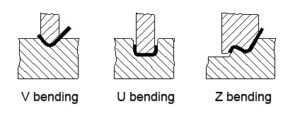
Common Bending Dies
Common bending dies are shown as below. In order to prolong the life of the dies, rounded corners should be used in part design whenever possible.
If the flange height is too small, it is not conducive to forming even with bending dies. Generally the flange height L≥3t (including wall thickness).
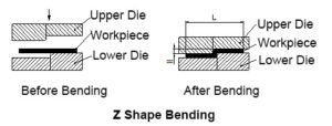
Processing Methods for Stepped Transitions
For some low-height stepped Z-bends in sheet metal parts, manufacturers often use simple dies on punch presses or hydraulic presses for small batch processing. It can also be processed on a bending machine using stepped dies as shown below. However, the height H cannot be too high, and should generally be in the range of (0~1.0)t. If the height is (1.0~4.0)t, the removable insert die structure should be considered based on actual conditions.
The die height can be adjusted by adding shims, so H can be adjusted arbitrarily. But there is also a disadvantage that the length L is not easy to control, and the verticality of the vertical edge is not easy to ensure. If H is very large, bending on a bending machine should be considered.
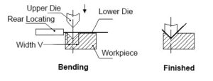
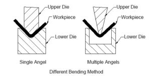
There are two bending machines, common bending and CNC bending machines. Due to higher precision requirements and irregular bending shapes, sheet metal bending for communication equipment is generally done on CNC bending machines. The basic principle is using the bending blade (upper die) and V-shaped groove (lower die) of the bending machine to bend and form the sheet metal part.
Advantages: Easy clamping, accurate positioning, fast processing speed;
Disadvantages: Low pressure, can only process simple shapes, lower efficiency.
Basic Principles of Forming
The basic principles of forming are shown below:
Bending Blade
Upper Die
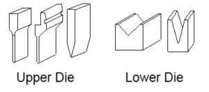
Bending blade forms are shown below. In processing, the selection is mainly based on the shape requirements of the workpiece. Manufacturers generally have a wide variety of bending blade shapes, especially highly specialized manufacturers. In order to process various complex bends, many custom bending blades with different shapes and sizes are made.
Lower Die
Generally V=6t (t is material thickness)
There are many factors affecting bending process, mainly including upper die arc radius, material, thickness, lower die strength, lower die mouth size, etc. To meet product requirements while ensuring safe use of bending machines, manufacturers have standardized bending die models. We need a general understanding of existing bending dies during structural design. The left side below shows the upper die, and the right side shows the lower die.
Basic Principles of Bending Sequence:
(1) Bend from inside to outside;
(2) Bend from small to large;
(3) Bend special shapes first, then general shapes;
(4) The preceding process does not affect or interfere with subsequent processes after shaping.
Current bending forms are generally as shown below:
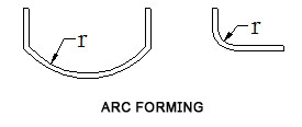
Bending Radius
A bending radius is required at the bending position during sheet metal bending. The bending radius should not be too large or too small, and should be appropriately selected. A bending radius that is too small can easily cause cracks at the bending position, while a radius that is too large can cause easy springback after bending.
The preferred bending radii (inner radius) for different materials and thicknesses are shown in the table below.
- Minimum Bending Radius Value (mm)
| material | Annealed | Work-hardened | ||
| The relative position between the bending line and the fiber direction | ||||
| Perpendicular | Parallel | Perpendicular | Parallel | |
| 08、10、 | 0.1 t | 0.4 t | 0.4 t | 0.8t |
| 15、20、 | 0.1 t | 0.5t | 0.5 t | 1.0 t |
| 25、30、 | 0.2 t | 0.6 t | 0.6 t | 1.2 t |
| 45、50 | 0.5 t | 1.0 t | 1.0 t | 1.7 t |
| 65Mn | 1.0 t | 2.0 t | 2.0 t | 3.0 t |
| Aluminum | 0.1 t | 0.35 t | 0.5 t | 1.0 t |
| SUS | 0.25 t | 0.5 t | 0.5 t | 1.5 t |
The data in the table are preferred values for reference only. In actual situations, the fillet radius of manufacturer’s bending dies is usually 0.3, with a small number of 0.5.
For ordinary low carbon steel plates, stainless aluminum plates, brass plates, copper plates, etc., an inner fillet radius of 0.2 is generally not a problem, but for some high carbon steels, hard aluminum, ultra hard aluminum, such a bending radius can lead to bending fractures or cracks at the outer fillet.
Bending Springback
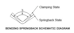
Springback angle Δα=b-a
Where b is the actual angle after springback; a is the die angle.
Magnitude of Springback Angle
Springback angle for 90 degree single bend free bending is shown in the table below.
- Springback angle for 90 degree
| Material | r/t | Material thickness t(mm) | ||
| <0.8 | 0.8-2 | >2 | ||
| Low carbon steel | <1
1-5 >5 |
4°
5° 6° |
2°
3° 4° |
0°
1° 2° |
| Mid carbon steel | <1
1-5 >5 |
5°
6° 8° |
2°
3° 5° |
0°
1° 3° |
| High carbon steel | <1
1-5 >5 |
7°
9° 12° |
4°
5° 7° |
2°
3° 6° |
Factors Affecting Springback and Measures to Reduce Springback
- Mechanical properties of material
The springback angle is proportional to the material yield point, and inversely proportional to Young’s modulus E. For sheet metal parts with high precision requirements, low carbon steel should be selected to reduce springback, instead of high carbon steel, stainless steel, etc.
- The larger the relative bending radius r/t, the smaller the deformation, and the larger the springback angle Δα.
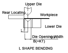
Minimum flange calculation for single bend
The initial state of L-shaped bending is shown in the figure below:
- Table for Inner R and Minimum Bending Height of Cold Rolled Metal Sheet
| NO. | Thickness | Die Width | Punch R | Minimum Bending Height |
| 1 | 0.5 | 4 | 0.2 | 3 |
| 2 | 0.6 | 4 | 0.2 | 3.2 |
| 3 | 0.8 | 5 | 0.8 or 0.2 | 3.7 |
| 4 | 1.0 | 6 | 1 or 0.2 | 4.4 |
| 5 | 1.2 | 8 or 6 | 1 or 0.2 | 5.5 or 4.5 |
| 6 | 1.5 | 10 or 8 | 1 or 0.2 | 6.8 or 5.8 |
| 7 | 2.0 | 12 | 1.5 or 0.5 | 8.3 |
| 8 | 2.5 | 16 or 14 | 1.5 or 0.5 | 10.7 or 9.7 |
| 9 | 3.0 | 18 | 2 or 0.5 | 12.1 |
| 10 | 3.5 | 20 | 2 | 13.5 |
| 11 | 4.0 | 25 | 3 | 16.5 |
The initial state of Z-shaped bending is shown in the figure below:

The minimum bending flange size L for Z-shaped bending of sheet metal with different thicknesses is shown in the table below:
- Z shape bending minimum height
| NO. | Thickness | Die Width | Punch R | Z Bending Height L |
| 1 | 0.5 | 4 | 0.2 | 8.5 |
| 2 | 0.6 | 4 | 0.2 | 8.8 |
| 3 | 0.8 | 5 | 0.8 or 0.2 | 9.5 |
| 4 | 1.0 | 6 | 1 or 0.2 | 10.4 |
| 5 | 1.2 | 8 or 6 | 1 or 0.2 | 11.7 or 10.7 |
| 6 | 1.5 | 10 or 8 | 1 or 0.2 | 13.3 or 12.3 |
| 7 | 2.0 | 12 | 1.5 or 0.5 | 14.3 |
| 8 | 2.5 | 16 or 14 | 1.5 or 0.5 | 18.2 or 17.2 |
| 9 | 3.0 | 18 | 2 or 0.5 | 20.1 |
| 10 | 3.5 | 20 | 2 | 22 |
| 11 | 4.0 | 25 | 3 | 25.5 |

Leave A Comment